


Contributors
Subscribe to our newsletter
Impact-echo is an acoustic non-destructive test (NDT) method developed by Sansalone and Carino1 in the 1980s for flaw detection in plate-like concrete structures, such as bridge decks, walls, and slabs. Internal flaws such as cracks, voids, honeycombing, and delamination can negatively impact the capacity and service life of concrete structures. Nondestructive evaluation (NDE) is critical for investigating the presence and extent of such defects that cannot be identified using visual inspection, and should be conducted prior to intrusive or destructive tests.
Basic Principle
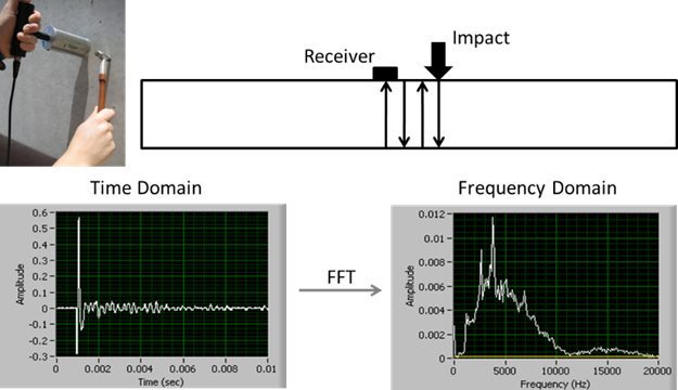
To conduct an impact-echo test, a small, short-duration impact is made on the surface of the concrete, which causes ultrasonic stress waves to propagate out from the impact point and travel back and forth between the impacted surface and opposite surface, as well as internal flaws. A displacement transducer (the receiver in Fig. 1) located near the impact records the subsequent vibrations of the concrete perpendicular to the surface. The displacement vs. time data is recorded by a data acquisition system. This so-called “time domain” data is then processed using a Fast-Fourier Transform (FFT), which converts and presents the data as a spectrum in the frequency domain for analysis, as shown in Fig. 1.*
P-wave velocity & Thickness Measurements (ASTM C1383)
There is a mathematical relationship between the peak (highest amplitude) frequency, the speed of sound in the concrete (P-wave velocity), and the thickness of the concrete. Thus, calculations of P-wave velocity and thickness can be made from impact-echo test results on plate-like structures. This has been standardized in ASTM C13832, which defines plate-like structures as those with an aspect ratio (least lateral dimension/thickness) of 6 or greater. If the P-wave velocity (VP) of the material is unknown, it can be determined with an impact and two transducers located at fixed distances from the impact and measuring the relative arrival times of the generated P-waves. The thickness can then be determined with an impact-echo test with the following equation:
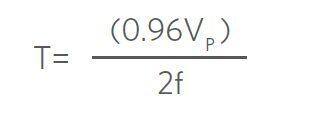
In the above equation, f is the peak frequency in Hz identified in the frequency domain. The P-wave velocity is multiplied by a “shape factor” of 0.96 because in plates, a particular vibrational mode called the thickness mode is excited by the repeated P-wave reflections; it is the frequency of these vibrations that is detected by the transducer, and they correspond to approximately 96% of the actual P-wave velocity of the material. Such shape factors can also be determined for analyzing impact-echo tests of prismatic structural elements (e.g. square, circular cross-section columns and beams), though they are not covered by ASTM C1383.
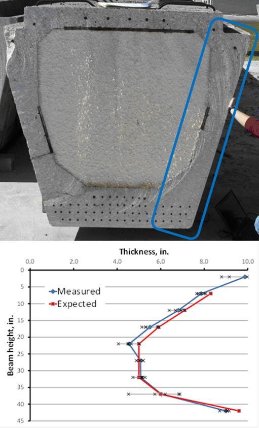
Measuring P-wave velocity provides an indication of the relative quality of the concrete; higher velocities tend to correlate to better quality concrete. By mapping the measured velocities from an array of test locations, variations in concrete quality can be visualized and local regions of degradation can be located in a given structure. The same can be done for thickness measurements, if there are concerns about variability in thickness or the location of an internal void (e.g. in a hollow-core girder, Fig. 2).
Flaw Detection with Impact-Echo
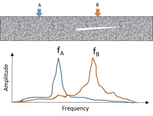
Flaw detection with impact-echo generally uses the same principle as thickness measurements. Where there is a discrete flaw located below the impact point, if the flaw is large enough, there will be nearly complete reflection of the P-waves by the flaw, rather than the opposite surface. This scenario is illustrated in Fig. 3, where the peak frequency for test at location ‘B’ above the flaw is much higher than the peak frequency for location ‘A.’ The higher peak frequency not only indicates the presence of a flaw, but also its depth. Smaller flaws permit most of the reflecting waves to travel around them; this increases the travel path, resulting in an apparent reduction in velocity and evident as a shift to a slightly lower peak frequency. Such flaws are more difficult to detect and require baseline data from an undamaged section of the structure. Large, shallow flaws, such as a delamination at the first layer of reinforcement, may also exhibit a very low peak frequency, known as the “drum effect”; this caused by flexural vibration of the near-surface concrete above the flaw and the peak frequency cannot be used to measure the flaw depth. Finally, distributed cracking, such as that produced by freezing and thawing or ASR, may be detectable by a combination of a shift to a lower peak frequency, and a frequency spectrum that is “noisy” with a less-defined primary peak. Further guidance and examples of flaw detection with impact-echo, including the effect of flaw size and depth, and the influence of impactor type, are provided by ACI3, Carino4, and Henriksen5.
Applicable ASTM standards include C1383, Standard Test Method for Measuring the P-Wave Speed and the Thickness of Concrete Plates Using the Impact-Echo Method.
* While pulse-echo systems exist that simply measure the out-and-back travel time of ultrasonic waves (time domain analysis), they are impractical for plate-like structures. Pulse-echo systems are better suited to long, thin structures such as foundation piles and drilled shafts where return times are longer than the impact duration.
Citations
1. Sansalone, M., and Carino, N.J., (1986) “Impact-Echo: A Method for Flaw Detection in Concrete Using Transient Stress Waves,” NBSIR 86-3452, National Bureau of Standards, Sept., 222 p. (Available from NTIS, Springfield, VA, 22161, PB #87-104444/AS)
2. ASTM C1383-15, “Standard Test Method for Measuring the P-Wave Speed and the Thickness of Concrete Plates Using the Impact-Echo Method,” ASTM International, West Conshohocken, PA, 2015, www.astm.org. DOI: 10.1520/C1383-15
3. ACI Committee 228 (2013) ACI 228.2R-13: Report on Nondestructive Test Methods for Evaluation of Concrete in Structures, American Concrete Institute.
4. Carino, N.J. (2015), “Impact Echo: The Fundamentals,” International Symposium on Nondestructive Testing in Civil Engineering (NDT-CE), September 15-17, 2015, Berlin. www.ndt.net/?id=18424
5. Henriksen, C (1995) “Impact-echo Testing,” Concrete International 17(5):55-58.
This summary description is offered for educational purposes only and no warranty (express or implied) is given on the applicability of this information to any particular part, material, application, or product. This article is not intended to be a complete dissertation on this topic and the reader is encouraged to contact RJ Lee Group for consultation regarding individual applications, materials, or situations.
This summary description is offered for educational purposes only and no warranty (express or implied) is given on the applicability of this information to any particular part, material, application, or product. This article is not intended to be a complete dissertation on this topic and the reader is encouraged to contact RJ Lee Group for consultation regarding individual applications, materials, or situations.
Applicable RJLG Services
Non-destructive Testing & Evaluation
Field Evaluations & Structural Assessment
Petrography
Targeted Sample Collection
Related RJLG Project Examples
Concrete Railroad Ties
Concrete Pavements
Parking Decks & Lots
Bridges, Sidewalks, Retaining Walls & Floor Slabs
