Contributors
Subscribe to our newsletter
Written By: Eric R. Giannini, Ph.D., P.E.
Ultrasonic pulse velocity (UPV) is an acoustic non-destructive test (NDT) method most often used to evaluate the relative quality, or uniformity, of concrete structures, and to identify the presence of internal flaws such as cracks, voids, and honeycombing. UPV can also be used to assess the severity of damage from durability-related distresses (e.g. ASR), to estimate the depth of surface-breaking cracks, and to monitor structures for changes in their condition over time.
Basic Principle of UPV
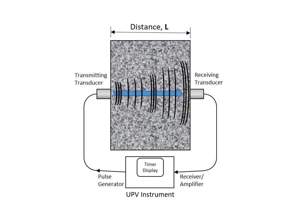
To conduct an UPV test, the travel time of an ultrasonic (frequency > 20 kHz) pulse through a known thickness of concrete is measured. The pulse velocity is calculated as the distance traveled divided by the travel time. The UPV instrument is a portable unit containing an electrical pulse generator, a pulse receiver/amplifier, a timer (typically with 0.1 µs resolution), and timer display. The instrument employs two piezoelectric transducers; one transducer converts the electrical pulse to a mechanical vibration (the ultrasonic pulse) that is transmitted into the concrete, while the receiving transducer converts the received pulse to an electrical pulse that returns to the instrument, stopping the timer. The transducers are coupled to the concrete with a viscous fluid or gel to maximize transmission of the pulse energy.
The test is typically conducted with transducers located on opposite sides of the concrete element being tested, which is known as the through-transmission, or direct configuration, illustrated in Fig. 1. The test can also be conducted with the transducers on surfaces oriented at right angles to each other (semi-direct configuration), or with both transducers on the same surface (indirect configuration), when access to opposing surfaces is not feasible.
An ultrasonic pulse is generated travels through the concrete as a combination of acoustic wave types; the compressional wave, or P-wave, travels faster than shear (S) or surface (R) waves, and is the first to arrive at the receiving transducer. Thus, the velocity measured is also referred to as the P-wave velocity, and the received pulse is referred to as the ‘first arrival,’ particularly if the instrument is connected to an oscilloscope to display the full received waveform. The slower-arriving S- and R-waves are not considered in UPV testing, but can be analyzed by other, more computationally intensive techniques.
Relationship to Mechanical Properties of Concrete
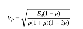
The P-wave velocity (VP) in concrete is a function of the dynamic modulus of elasticity (Ed), dynamic Poisson’s ratio (µ), and the density of the concrete (ρ) according to the following equation given in ASTM C597, Standard Test Method for Pulse Velocity Through Concrete:
The velocity measured by UPV is thus proportional to the square root of the dynamic modulus of elasticity, which describes the stress/strain behavior under rapidly applied small strains. The dynamic modulus is greater than, but still proportional to the static secant modulus, a property typically used in analysis of concrete structural behavior. The elastic modulus (stiffness) of concrete is also often assumed in design and analysis to be proportional to the square root of the compressive strength. Although this would seem to imply a fourth-power relationship between P-wave velocity and compressive strength, in practice, the relationship of P-wave velocity to compressive strength must be determined empirically for a particular concrete mixture. In addition to the influence of Poisson’s ratio and density (which are largely independent of strength or stiffness), velocity is determined from the shortest travel time between the two transducers, which is indicative of the best quality concrete traversed by the P-wave. However, it should be noted that strength is actually governed by the weakest pathway through the concrete1.
Factors Influencing UPV Test Results
In addition to the factors discussed above, UPV test results can also be influenced by the temperature and moisture condition of the concrete, as well as the transducer frequency, aggregate size, and the presence and orientation of reinforcing steel. For example, air-dried concrete with a high w/cm may exhibit an increase in P-wave velocity of 5% if it is saturated with water.Also, temperatures greater than 30°C (86°F) or less than 5°C (41°F) may require corrections to the result2. Moisture and temperature corrections are most important when attempting to estimate mechanical properties or when monitoring changes in a structure over time. The transducer frequency should be selected such that the wavelength is greater than the maximum aggregate size, but less than the least lateral dimension of the concrete element. In practice, 54 kHz transducers (74 mm wavelength for concrete with a pulse velocity of 4000 m/s) are commonly used with good results. Because the speed of sound in steel is significantly greater than that of concrete, the presence of reinforcing steel can lead to a higher measured velocity in the concrete, particularly when the steel is parallel to the path between the transducers. If possible, measurements should not be made in areas of dense reinforcement or parallel to the steel.
Use of UPV for Condition Assessment
Measuring P-wave velocity provides an indication of the relative quality of the concrete; higher velocities tend to correlate to better quality concrete. Lower velocities can be indicative of internal cracks and flaws that slow the P-waves or force them to take a longer path, as indicated by cases (b) and (c) in Fig. 2. The complete absence of a received pulse indicates more significant voids and cracks that cause a complete reflection of the pulse (case (d) in Fig. 2). Fig. 3 shows test data from concrete damaged by alkali-silica reaction (ASR) and delayed ettringite formation (DEF), forms of durability distress that involve distributed internal cracking that can greatly reduce the stiffness of the concrete; this is manifested in UPV results by velocity reductions of up to 20% compared to undamaged concrete. By mapping the measured velocities from an array of test locations, variations in concrete quality can be visualized and local regions of degradation can be located in a given structure, while long-term monitoring will provide information on the progress of damage development.
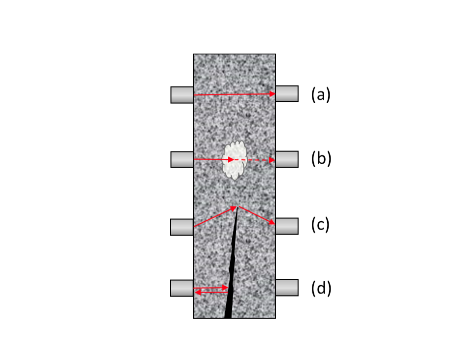
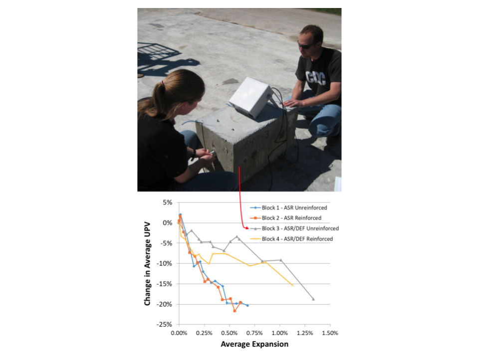 Fig 3 – Through-transmission UPV test results for concrete specimens experiencing expansion and cracking from ASR and DEF.6
Strength estimation is possible with UPV, following methodologies given by ACI3 and Naik et al.2 for new construction and existing concrete structures. These require developing empirical mixture-specific correlations between compressive strength and P-wave velocity. Combined methods involving both UPV and the rebound hammer (e.g. SONREB) may provide small improvements in the reliability of strength estimates and have seen more widespread use in Europe4.
UPV testing in the indirect configuration (both transducers on the same surface) can also be used for the purpose of estimating the depth of open surface-breaking cracks, and the thickness of a damaged surface layer of concrete.2,5
By identifying areas likely to contain defects and variations in concrete quality that cannot be detected with visual inspection, nondestructive evaluation (NDE) of concrete structures with UPV can inform sampling plans for more intrusive investigations, such as core extraction for petrography and mechanical testing.
ASTM Standards
- C597 – Standard Test Method for Pulse Velocity through Concrete
- C823 – Standard Practice for Examination and Sampling of Hardened Concrete in Constructions
This summary description is offered for educational purposes only and no warranty (express or implied) is given on the applicability of this information to any particular part, material, application, or product. This article is not intended to be a complete dissertation on this topic and the reader is encouraged to contact RJ Lee Group for consultation regarding individual applications, materials, or situations.
Applicable RJLG Services
Nondestructive Testing & Evaluation
Field Evaluations & Structural Assessment
Petrography
Targeted Sample Collection
References
1Teodoru, G.V.M. (1994), “Nondestructive Testing of Concrete from the Research to the Use in the Practice.” In International Advances in Nondestructive Testing, Volume 17, by W. McGonnangle, 117-138. Gordon and Breach, Langhorne, PA.
2 Naik, T.R.; Malhotra, V. M.; and Popovics, J. S. (2004), “The Ultrasonic Pulse Velocity Method,” Handbook on Nondestructive Testing of Concrete, V. M. Malhotra and N. J. Carino, eds., CRC Press, Boca Raton, FL.
3ACI Committee 228 (2019), ACI 228.1R-19: Report on Methods for Estimating In-Place Concrete Strength, American Concrete Institute, Farmington Hills, MI.
4Samarin, A. (2004), “Combined Methods,” Handbook on Nondestructive Testing of Concrete, V. M. Malhotra and N. J. Carino, eds., CRC Press, Boca Raton, FL.
5 ACI Committee 228 (2013), ACI 228.2R-13: Report on Nondestructive Test Methods for Evaluation of Concrete in Structures, American Concrete Institute, Farmington Hills, MI.
6Giannini, E.R. (2012), Evaluation of Concrete Structures Affected by Alkali-Silica Reaction and Delayed Ettringite Formation, Ph.D. Dissertation, The University of Texas at Austin, Austin, TX.